First I want to apologize for the break without making a post, remember when I wrote in the post "A museum was the incentive for my restart in model making" there I commented in a paragraph about moments that make me want to give up. That's what happened in the last few days, my workbench came to accumulate dust. But today I decided to clean everything up and finish the last element of my diorama, the air compressor.
Next, I will report my experience in doing the whole process: 1) research, 2) modeling, 3) 3D printing, 4) painting and 5) weathering.
1) Searching the model
When I decide that my workshop diorama needs an air compressor. I did a search to get 2D internet drawings to reference the model time.
These drawings come in the equipment's manuals with some measurements that are very important at the time of modeling.

I printed the schematic and used the measurements from the manual to convert the scale, for the additional measurements I used my digital caliper.
As my diorama is at 1:25 scale, a lot of things that are in the schematic will disappear, so I chose to highlight the parts that could characterize the object, even so small.
2) Modeling

To make the modeling I used the opensource software Freecad
The software use the parametric method, ie used all the actions that you do are recorded into a transformation tree.
Note that in the drawing I did not model the parts that are repeated, because for these parts I printed two copies.
In addition, the model does not include the protection for the belt, because for it I used a technique during printing.
To make the top part of the compressor block I chose a 2D sketch followed by a revolve function, to rotate the sketch 180 degrees.

My goal here is not to teach you how to use a CAD tool, for that there are several free youtube courses to get you started in Freecad. On the other hand, I intend to give practical tips on how I performed the modeling.
Once the sketch is drawn in 2D on the Sketcher bench in Freecad. I moved to the Part Design bench to make the object revolution


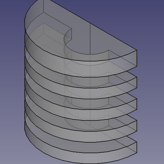

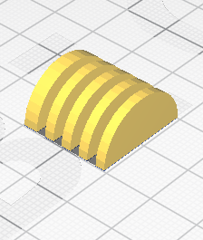
At the time of printing, I laid the piece with the cut side on the table, so the print didn't need support, I made two copies and join them.
At the base of the compressor block, 3 parts were used, a hub for the structure, a cylinder to make the detail through which the pulley axis passes and a trapeze for the side details. As I am working with a very reduced scale, I chose to simplify the drawing. To make a trapeze I used the sketcher bench again.
In short:
I drew the trapeze sketch
I made the extrusion
then I drew the box and the cylinder
I joined the trapeze with the box and then with the cylinder.


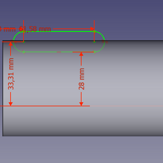
The next step was to model the base of the motor and compressor. In this modeling, the shape of the compressor cylinder was necessary, 2 box a model inside the other and a sketch to make a box with rounded edges, make cutouts, and feet of the base.
Follow the steps:
Sketch in the shape of the feet that will be cut from the base of the engine
sketch extrusion
from the inside of the base with two can be one inside the other.
Cutout of the motor base feet with a rectangular piece with rounded corners
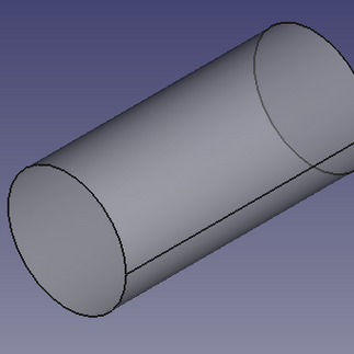
Duplicate the cylinder and then use it as an air cylinder for the compressor
Cut out one of the copies of the cylinder and the base for consulting


For the engine, I ended up making two versions, the first one full of details, but when it was time to print the scale it wasn't good, so I made a simpler version of 4 objects.
I started with a cylinder for the motor housing, a sketch for the coil, a sketch for the base and finally two cylinders for the pulley. As per the images below


To make the big pulley I drew a sketch of a circle with three trapezoids inside. The method I used was:
draw 2 objects with 8 edges (octagon), one being bigger and one smaller
erase 4 edges from both objects
then join the edges of the two objects forming these trapezoids
drawing a circle on the outside to limit the pulley
pulley extrusion


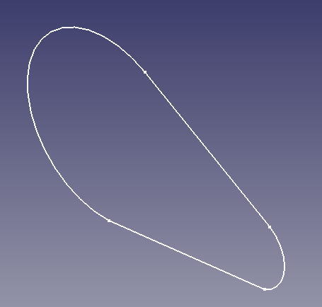
The belt was drawn from a sketch formed of two circles, a smaller one for the larger pulley and another smaller one for the motor pulley.
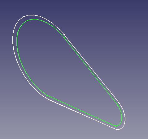
To transform the sketch into 3D, I duplicated the sketch, reduced the scale and extruded both parts, and then subtracted one from the other.
I took the opportunity to make a copy of the larger one to use as a belt protection.


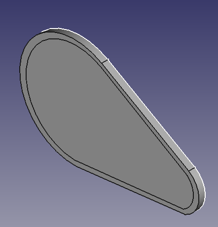

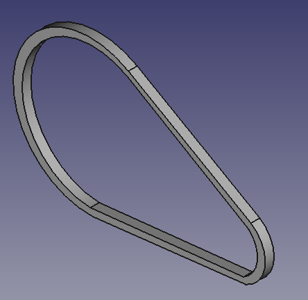
For the protecter the belt in the form of a grid, I used a resource when slicing in Cura.
As I mentioned earlier, I made a copy of the larger object that I used to make the belt. When slicing, I removed the top and bottom layers of the object, so Cura sliced only the outer walls and the fill.

The last objects that still need to be modeled are references to the compressed air cylinder.
I solved to do designed the objetcts separated to avoid supports and also leave a vertical impression so that the layers of the printing would portray the shape of the objects.


3) 3D printing
After this 3D coining step, I started printing the parts. For this I used PLA Easyfill. This PLA has a feature of slightly reducing the grooves between the print layers, giving a slightly smoother appearance to the part.

Note that for the parts I use Brim to help glue the print bed.
For the feet I have an interesting idea to print them. I increased the size of the Brim so that the pieces were together, when gluing it to the cylinder I applied instant glue on each foot and glued it to the cylinder at once. After drying, I removed the Brim from the feet with the help of a small pair of scissors. That way, the distance between the feet was as I had modeled it in 3D.
4) Painting
The next phase was to unite the pieces of the same color, and then paint them. It is important to point out that I made a white mask in the place where the decal goes so that the colors of the decal are preserved and not suffer the influence of the background color.


Another thing I forgot to mention was how I made the hose. For this I used the manual extrusion of the printer's filament, the one we use when need to change the filament. I took a piece of hot filament from the printer and with the help of tweezers I rolled it up to form the hose. I admit that it took several attempts to reach a legal result.
The same was done for the copper connection that connects the compressor to the cylinder.
After assembled and painted the 1:25 scale compressor was as follows.
In the first photo without and the second with the weathering.


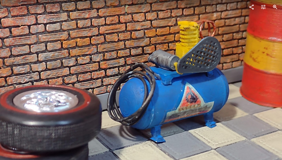
5) Weathering
For the aging process I used an oil-based washing mixture with brown, yellow and black. But I made a primary mistake, I forgot to apply the acrylic varnish over the decal. To make this type of decal as in the post How to make an Oil Barrel for your diorama in 7 steps, I stylized solvent-based varnish to make the decal film and that's why it's necessary in this case, apply the acrylic varnish on top to not to smudge the decal when it comes in contact with the washing mixture. But as the proposal of the piece is to be worn out, I decided to leave it that way.
This was the last piece for the diorama, now it's just a matter of gluing everything and showing it here on mozayco.com.
I'm really looking forward to seeing how the final result turns out.